
Posted by Electric Solenoid Valves on Apr 2nd 2026
How to Wire a Pneumatic Solenoid Valve — 24V DC and 110V AC Guide
How to Wire a Pneumatic Solenoid Valve Safely and Correctly
A Pneumatic Solenoid Valve must be wired correctly before it can switch reliably in a compressed air system. If the coil voltage is wrong, the DIN connector is wired poorly, or the air supply is not within the valve’s operating range, the valve may fail to actuate or perform inconsistently.
This guide explains how to wire a pneumatic solenoid valve with a DIN-style connector, what to check before energizing the coil, and what to do if the valve does not shift after startup. It is written around the pneumatic valve models available at Electric Solenoid Valves, including 24V DC and 110V AC options.
If you are still selecting a valve rather than wiring one, browse our pneumatic solenoid valve collection first to confirm the correct configuration, port size, and voltage.
| SHOP PNEUMATIC SOLENOID VALVES |
What to Check Before Wiring a Pneumatic Solenoid Valve
Before connecting power, confirm the basics. Many startup problems happen because the wrong supply voltage is used, the connector is assembled incorrectly, or the valve is installed in a system that does not meet its pressure requirements.
- Coil voltage - Check whether the valve is rated for 24V DC or 110V AC.
- Connector style - Confirm the valve uses a DIN-style coil connector.
- Power source - Verify the available supply matches the coil rating exactly.
- Pressure range - Confirm the compressed air system falls within the valve’s operating range.
- Valve type - Make sure the installed valve matches the application, such as a 3-way valve for single-acting cylinders or a 5-port valve for double-acting cylinders.
- Safe isolation - Disconnect electrical power before opening the connector housing.
Do not assume that a valve problem is electrical only. A correctly wired coil still will not solve issues caused by low pressure, contamination, or incorrect valve selection.
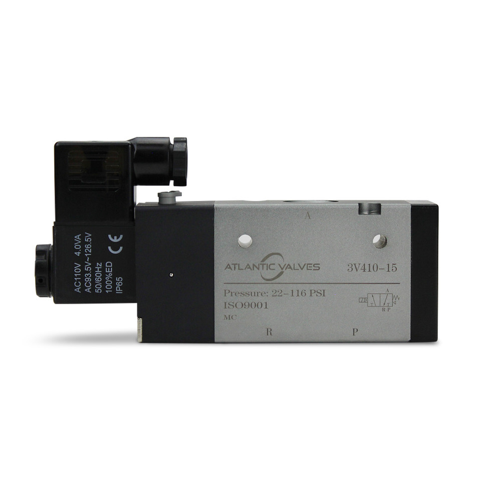
24V DC vs 110V AC Pneumatic Solenoid Valve Coils
One of the first things to verify is the coil voltage. Pneumatic solenoid valves are commonly supplied with either 24V DC or 110V AC coils, and each is used in different control environments.
24V DC Coils
24V DC is common in control panels, PLC-based automation systems, and low-voltage installations. It is often preferred where safer low-voltage control circuits are required or where the valve is tied into industrial automation logic.
110V AC Coils
110V AC is often used where standard mains power is readily available, and no separate low-voltage supply is needed. This can simplify installation in some facilities, but the supply must still match the coil exactly.
Do not energize a coil until the voltage is confirmed. Applying the wrong voltage can damage the coil, create overheating issues, or prevent the valve from actuating at all.
Quick Comparison
| Coil Option | Common Use | Main Advantage | Main Check |
|---|---|---|---|
| 24V DC | PLCs, control panels, automation systems | Low-voltage control compatibility | Match the supply polarity convention and confirm the output voltage |
| 110V AC | Facilities with standard mains power | Easy integration where AC power is already present | Confirm correct AC supply and grounding where applicable |
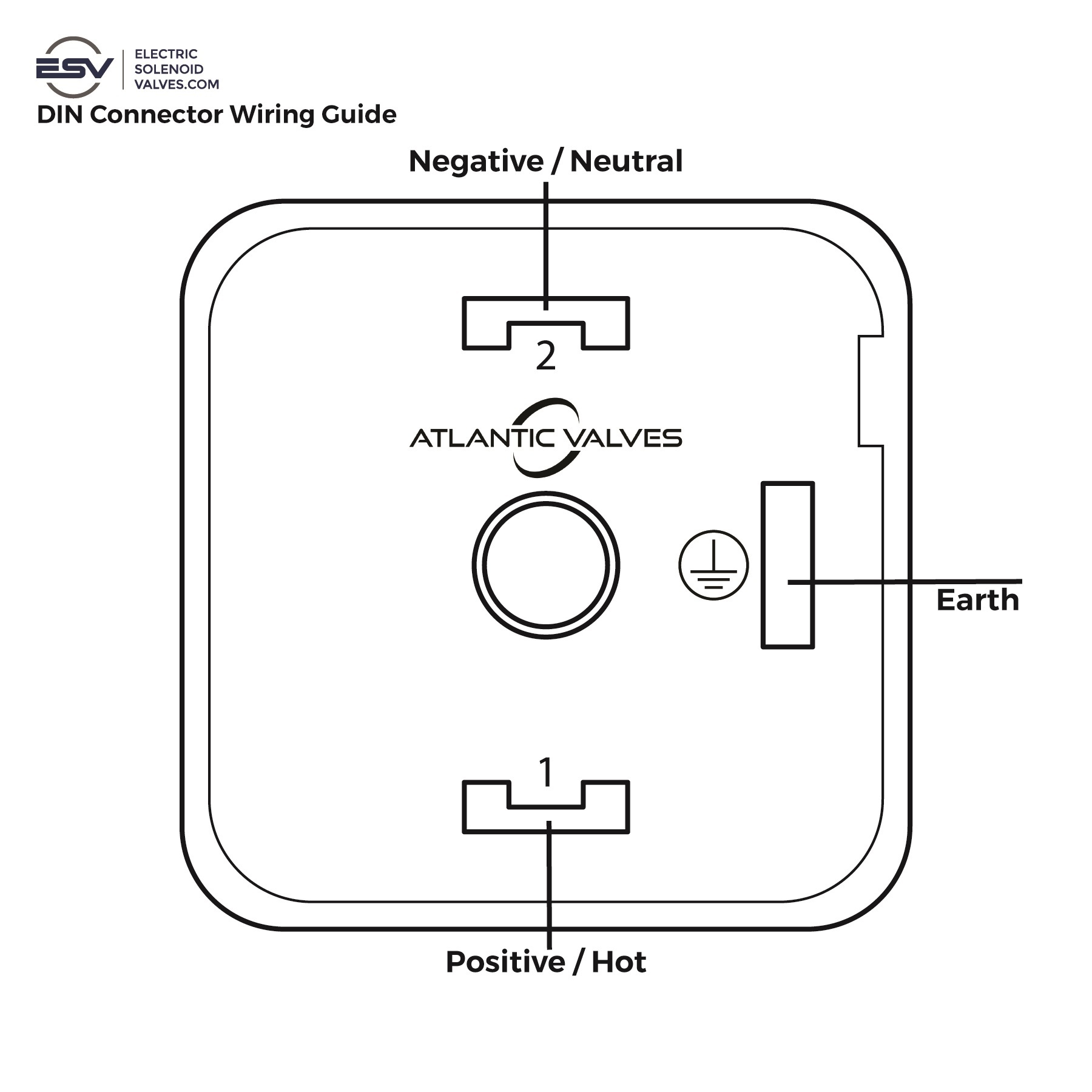
How to Wire a DIN-Style Pneumatic Solenoid Valve
Many pneumatic solenoid valves use a DIN-style connector mounted directly to the coil. The exact connector design can vary by model, but the general process is straightforward if the supply voltage and terminal layout are confirmed first.
- Disconnect power before starting.
Shut off the electrical supply and verify the circuit is safe before opening the connector. - Remove the DIN connector.
Loosen the connector screw and pull the connector body away from the coil. - Open the connector housing.
Access the internal terminal area so the wires can be connected securely. - Connect the wires to the correct terminals.
Terminal 1 is commonly used for the positive supply for consistency. Terminal 2 is used for the negative supply. The earth terminal is used for grounding on AC installations where applicable. - Reassemble the connector.
After the wires are secured, close the housing and reinstall the connector onto the coil. - Restore power and test the valve.
Energize the coil and verify that the valve actuates correctly under normal system pressure.
Important note:
On the pneumatic valve models this guide is based on, the coil is non-polarized, so Terminals 1 and 2 can typically be swapped. Even so, using Terminal 1 for positive as a standard practice helps keep installations consistent and easier to troubleshoot later.
Pneumatic Solenoid Valve Wiring Terminal Basics
DIN connector terminals are simple, but confusion here can still create installation mistakes. Always verify the terminal markings on the actual connector before applying power.
- Terminal 1 - Commonly used for positive supply as a standard wiring convention.
- Terminal 2 - Commonly used for negative supply.
- Earth terminal - Used for grounding where required, especially on AC installations.
Some installers assume polarity is always critical. On many pneumatic solenoid valve coils, that is not the case. But consistency still matters. Clean, repeatable wiring practices make later service faster and reduce confusion when multiple valves are installed in the same panel or machine.
Common Wiring Mistakes That Prevent the Valve from Actuating
If the valve does not respond after installation, start with the wiring basics before assuming the valve has failed.
- Wrong coil voltage - A 24V DC coil connected to 110V AC, or the reverse, can cause immediate failure or no actuation.
- Loose terminal connections - Poor contact inside the DIN connector can interrupt power to the coil.
- Damaged connector components - Broken housing parts, worn seals, or bent contact points can prevent reliable connection.
- Improper grounding on AC installations - The earth connection should be checked where applicable.
- No output from the control circuit - The issue may be upstream in the PLC, switch, relay, or power supply.
- Assuming the problem is only electrical, even a correctly wired valve may not shift if the air pressure is below the minimum operating requirement.
What to Check if the Valve Still Does Not Shift
Once the wiring has been verified, move on to the most common non-electrical causes.
1. Verify Voltage at the Coil
Use a meter to confirm the rated voltage is actually reaching the connector when the valve is commanded to energize.
2. Confirm System Pressure Is Within Range
If the valve requires a minimum operating pressure and the system does not meet it, the valve may not actuate properly.
3. Inspect for Contamination
Debris inside the valve can interfere with spool movement and cause sticking or incomplete shifting.
4. Check Air Quality
Dirty or wet compressed air can shorten seal life and contribute to spool sticking. Upstream filtration and moisture separation help protect pneumatic valves in service.
If you need a deeper diagnostic walkthrough, see our related resource on common pneumatic solenoid valve problems and troubleshooting.
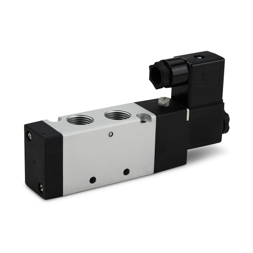
3-Way vs 5-Port Pneumatic Solenoid Valves, Quick Application Note
This article is focused on wiring, but valve type still matters because the wrong configuration can create operating problems even when the wiring is correct.
- 3-way pneumatic valves are generally used for single-acting cylinders where one powered motion direction is needed.
- 5-port pneumatic valves are generally used for double-acting cylinders where both extension and retraction are powered by compressed air.
If the system behavior does not match the actuator requirement, review the valve configuration before reworking the wiring.
When to Contact Technical Support
If the valve still does not actuate after you verify voltage, terminal connections, pressure, and air supply quality, the next step is to review the valve model itself. In some cases, the issue is not a failed coil but a mismatch between the valve type, port size, actuator, and system conditions.
That is where technical support can save time. It is better to confirm the correct configuration early than to keep replacing parts without solving the real problem.
Support line: Call 800-983-8230 or email sales@electricsolenoidvalves.com.
| BROWSE PNEUMATIC SOLENOID VALVE RANGE |
Conclusion
Knowing how to wire a pneumatic solenoid valve correctly starts with the basics: confirm the coil voltage, verify the DIN connector terminals, isolate power before assembly, and test the valve under the correct air pressure. If the valve still does not actuate, check the supply voltage at the coil, confirm the pressure range, and inspect for contamination or poor air quality before assuming the valve has failed.
For 24V DC and 110V AC pneumatic valve models, a clean installation process helps reduce startup problems and makes future troubleshooting much easier. If you are still selecting a valve, explore our pneumatic solenoid valve range to match the right configuration to your application.
Still need help?
Contact us to speak to a valve expert.